Manual EVKB100
Table of Contents
- EVERET EVKB100 IP & SERIAL JOYSTICK PTZ Controller
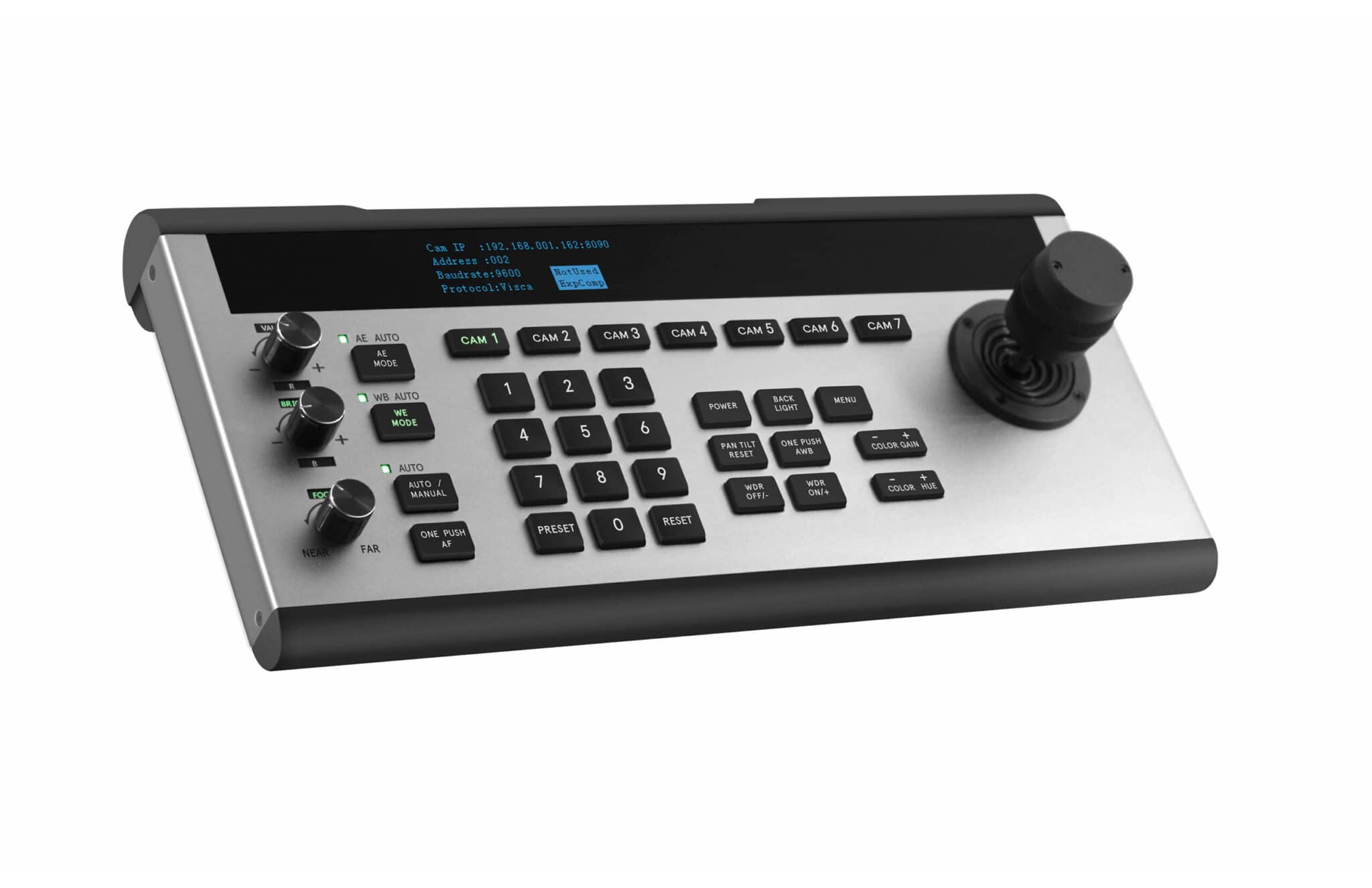
EVERET EVKB100 IP & SERIAL JOYSTICK PTZ Controller
PACKING LIST
Check all bellow items when you open the package:
| EVKB100 Controller | 1 |
| Power Adapter | 1 |
| Power Cable | 1 |
| RS422/485 Connectorblock | 1 |
NETWORK SECURITY
If you will use the controller connected to a network, your attention is asked. It is your responsibility to take precautions such as subscribed below to protect against network security risks.
- Avoid network connections using public lines
- Use the controller in a network secured by a firewall
- Protect your network against unauthorised access by restricting users to log in with an authorised user name and password.
QUICK START
- Connect the controller to your POE+ switch* or the included 12v Adapter.
- Enter the system settings of the controller by long pressing the menu button.
- Navigate with the joystick to the COM settings and move the joystick to the right to enter the COM Settings Menu.
- Make sure that every CAM you want to control has following setting:
CAM: 1~7
Address: 1
Baudrate: 9600
Protocol: VISCA
Move the Joystick to the right to save the setting after each adjustment.
- Navigate back to the Main menu by pressing the menu button or move the joystick to the left.
- Navigate to the Ethernet Settings to enter IP address of the cameras you want to control. Make sure that your cameras are in the same network as the controller. See manual of the camera for more information about this.
*Recommended switches
(POE+ IEEE 802.3af/at compliant with total power of 126W up to 30W per port)
Example recommended unmanaged POE+ network switches:
- 8-port: TL-SG1008MP
- 8-port: NETGEAR GS110TPP PoE+ Smart Switch
- 16-port: NETGEAR GS716TPP PoE+ Smart Switch
- 24-port: NETGEAR GS724TPP PoE+ Smart Switch
Example recommended managed POE+ network switches:
- 8-port: NETGEAR GSM4212P AV Line M4250-10G2F-PoE+
- 24-port: NETGEAR GSM4230P AV Line M4250-26G4F-PoE+
- 40-port: NETGEAR GSM4248P AV Line M4250-40G8F-PoE+
TECHNICAL SPECS
| Communication interfaces | RS485, RS422, RS232, RJ45 IP (UDP,TCP) |
| Baudrate | 2400, 4800, 9600, 19200, 38400 (Only for RS-422, RS-485, RS-232 |
| Protocol | VISCA, VISCA over IP, SONY VISCA , PELCO P/D |
| Camera Address | 1~255 |
| Display | OLED Display Screen |
| Camera Control | 7 |
| Joystick | 3-axis joystick (Pan/Tilt/Zoom) |
| Speed control | Yes |
| Zoom control | Yes |
| Auto Exposure | Yes |
| R/B Gain | Yes |
| Color Gain | Yes |
| Bright | Yes |
| Manual Focus /Autofocus/One push | Yes |
| Backlight | Yes |
| Power on/off camera | Yes |
| Control OSD Menu of camera | Yes |
| Presets | 128 |
| Power | Input AC100V ~ 240V Output DC 12V/2A |
| PoE | Yes |
| Power consumption | 24W |
| Working Temperature | 0°C ~ 40°C (32°F ~ 104°F) |
| Storage Temperature | -20°C ~ 60°C (-4°F ~ 140°F) |
| Weight | 2.10 KG |
| Dimensions (LxWxH) | 351mm x 173 mm x 99 mm |
Function Key Description

1. VALUE/R-Knobs

This knob is used to adjust the exposure parameters (Shutter and Iris) or the Red Gain when the camera is in manual white balance mode. Clockwise direct increases the value and counterclockwise direction decreases the value.
2. BRIGHT/B- Knobs

This knob is used to adjust the exposure parameters (Iris and Bright) or the Blue Gain when the camera is in manual white balance mode. Clockwise direct increases the value and counterclockwise direction decreases the value.
3. FOCUS Knobs

This knob is used to adjust the camera focus focal length. Clockwise direction increases focus focal length near and Counterclockwise direction adjusts the focus focal length Far. (When this function is used the camera automatically jumps to manual focus mode.
4. FOCUS Function Area

AUTO MANUAL: This button is used to switch between focus modes of the camera. Whether auto focus or manual focus. When the green light is on the camera is in AUTO MODE.
ONE PUSH AF: This button can only be used when the camera is in manual focus mode. By pressing this button the camera will one time auto focus and then remain in manual focus mode.
5. WB Mode Keys

The WB Mode button is used to change the White Balance Mod. By pressing the button the controlled camera will switch to AUTO or MANUAL mode. When the green light is on the WB is in AUTO mode. When the green light is off the WB is in MANUAL mode. See table below for an overview.
| WB Mode | Green Light | R-Knobs Function | B-Knobs Function |
| Auto | On | None | None |
| Manual | Off | Red Gain | Blue Gain |
6. AE Mode Keys

The AE mode button is used to switch between the different Exposure modes of the camera. See table below for more clarification. Out of the box the controller is in Auto mode. Press the AE MODE button each time you want to change the Exposure Mode.
| Exposure Mode | Green Light | VALUE-KNOB | BRIGHT-KNOB |
| Auto | ON | None | None |
| Manual | OFF | Shutter | Iris |
| Shutter Priority | OFF | Shutter | None |
| Iris Priority | OFF | Iris | None |
| Brightness Priority | OFF | None | Brightness |
7. PRESETS Function Area

The preset buttons are used to save, call and reset presets. In total 128 presets can be saved and called. See instructions below on how to SAVE, CALL and RESET a preset.
How to SAVE a preset?
How to CALL a preset?
- Press the number of the preset you want to call.
- Press the PRESET button and let go. (You will now see that the camera moves to the preset position)
How to RESET a preset?
- Press the RESET button and let go. (The green light of the RESET button starts blinking)
- Choose the preset number you want to reset, press it and let go.
- To confirm the reset of the preset, press the RESET button again and let go. (The green light is now off and the preset has been reset)
Camera function Area

POWER:
The POWER button has two functions.
- Check how many and which cameras are in working mode
- Switch the cameras to standby mode.
Check cameras in working mode:
- Press the power button to check how many cameras are in working mode. The CAM buttons 1-7 of the cameras that are in working mode will appear green. In the meantime the POWER button keeps blinking.
Switch cameras to standby mode:
- Meanwhile the green light of the cameras in working mode press and let go the CAM button you want to switch to standby mode. The CAM button light of the camera will now appear white. Follow the same process to switch the camera back to working mode.
PAN TILT RESET:
- Press this button to reset the pan tilt to the default position of the camera.
WDR OFF/- and WDR ON/+:
- Press the WDR OFF or WDR ON button to switch on/off the WDR function of the camera. Each time you press one of the buttons after the WDR the function is on or off it will increase or decrease the WDR Level.
NOTE: The WDR level can only be decreased when the WDR is OFF. To check if you have the right WDR level after decreasing you need to press the WDR ON/+ button to switch on the WDR function.
BACKLIGHT
- Press this button to turn on/off the backlight function of the camera.
ONE PUSH AWB
- Use this button to define what is white for the camera. You can do this by holding a white paper in front of the camera and press the ONE PUSH AWB button.
MENU
- Press this button one time and let go to enter the OSD menu of the selected camera. Press again to get exit the OSD Menu
- Long press this button until the menu of the controller appears on the display.
COLOR GAIN – +
- Each time the + button is pressed the color gain will increase
- Each time the – button is pressed the color gain will decrease
COLOR HUE – +
- Not supported
9. 3-Axis Joystick

The joystick supports Up/down, left/right and clockwise/ Counterclockwise direction rotation. It can control PTZ Camera UP/DOWN, LEFT/Right moving and Zoom in/Out. Clockwise rotation is Zoom in (TELE) and Counterclockwise direction rotation is Zoom out( WIDE). The sensitivity of the joystick can be adjusted in the menu of the controller.
10. Camera short Keys

These buttons are used to switch between the cameras connected to the controller. When a particular camera is selected the CAM button will turn green. At the same time the camera information will appear on the display.
IP address: x.x.x.x: 52381
Address: 1
Baudrate: 9600
Protocol: VISCA
11. Display Screen

The display of the controller is used to display the controller settings and information of the selected camera.
12. Light Sensor

The light sensor is only used when the backlight setting of the controller is set to AUTO. The sensor will detect the light condition in the room of the controller and automatically turn on/off the white backlight of the buttons. In this way the buttons will always stay visible.
Interface Function & Connection Diagram

13. Micro USB
The micro USB port is used for FW upgrades.
14. RS422/RS485 Interface
See diagram below to see instructions on how to connect a camera via RS422 or RS485.
| RS422 | RS485 | ||
| T+ | R+ | T+ | A+ |
| T- | R- | R- | B- |
| R+ | T+ | ||
| R- | T- |
15. RS232 Interface

See illustration below to see how to connect a camera via RS232.

16. LAN port
The LAN port is used to connect the controller to a PoE+ switch for Visca over IP control and Power over Ethernet.

16. 12V Power Interface
This is the 12V power input incase the adapter included is used.

Keyboard Menu Operation
Main menu
Please follow steps below to walk through the menu settings of the controller.
- Long Press the MENU button for over 3 seconds to enter the menu of the controller. The display will show menu options below.
| System settingCOM settingEthernet settingPassword setting |
- Move the joystick to the right to enter the submenu setting. After changing a submenu setting move the joystick to right to sav the setting.
- Move the joystick to left or press the menu button to exit submenu setting
- Move the joystick up/down to go through the menu and submenu settings.
- Press number keys 0-9 to enter number values of this is required.
System Settings
Move the joystick to the right to enter the system settings submenus and move the joystick up/down to scroll through the options.
| 1. Language: English 2. LED Brightness: Low| Normal| High 3. Back light: Auto| ON |Off 4. Joystick Sensitivity:1-7 5. Auto Standby: OFF 6. Itself IP:192.168.1.88:5000 7. About Keyboard |
Language
- Default language is English.
LED Brightness
- Adjust the LED brightness for the controller display: LOW/NORMAL/HIGH
Backlight
- This setting has influence on the backlight of the controller buttons. These are following options: AUTO/ON/OFF
When “AUTO” is selected, the controller will function according to environmental brightness
Joystick Sensitivity
- Adjust the speed of the PAN/TILT/ZOOM of the camera. The sensitivity can be set on scale from 1-7 with 1 as slowest movement and 7 as fastest movement.
Auto Standby
- The controller has a standby mode that can start after: 1min, 2mins, 5mins, 10mins, 20mins, 30mins, 60mins or never when this setting is turned off.
Itself IP Address
- Here you can change the IP address of the controller to make sure it is in the same range as the cameras connected. The port number can stay 5000.
About Keyboard
- Navigate to this submenu to check the controller information: Model No, FW version and Serial number.
COM Setting
Navigate with the joystick to COM Settings and move the joystick to the right to enter the submenus
| Channel: CAM 1-7 Address: 1 Baudrate: 9600 Protocol: VISCA |
Channel: CAM 1-7
- Choose which CAM channel you would like to configure
Address
- Default setting for all cameras when using Visca over IP: 1
- For PELCO P/D each camera should have different address: 1-7
Baudrate
- Default setting for all cameras when using Visca over IP: 9600
- In other cases the controller offer following baudrates: 2400 | 4800 | 19200 | 38400
Protocol
- Default setting for all cameras when using Visca over IP: VISCA
- In other cases the controller offers following protocols: SonyVisca | Pelco-D |Pelco-P
ETHERNET SETTING
Navigate to Ethernet setting and move the joystick to right to enter the submenus
| Channel: CAM 1-7 Cam IP: 192.168.x.x Port: 52381 Lock: Enabled |
Channel: CAM 1-7
– Choose which CAM channel you would like to configure
Cam IP
- Fill in the correct IP address with the number buttons on the keyboard. Move the joystick to the right to save until CAM IP is selected again.
Port
- Default: 52381
NOTE: Don’t change this number unless specifically instructed by Everet support.
Lock
- Default: enabled
NOTE: Don’t change this setting unless specially instructed by Everet support.\
Passwords Setting
Navigate to Password setting and move the joystick to right to enter the submenus
| Password enable: Disabled Modify password |
Password Enable
- Enable is disable password.
NOTE: Default Password: 8888
Modify Password
- Modify current password by entering default password -> entering new password -> confirming new password.