User Manual EVP220
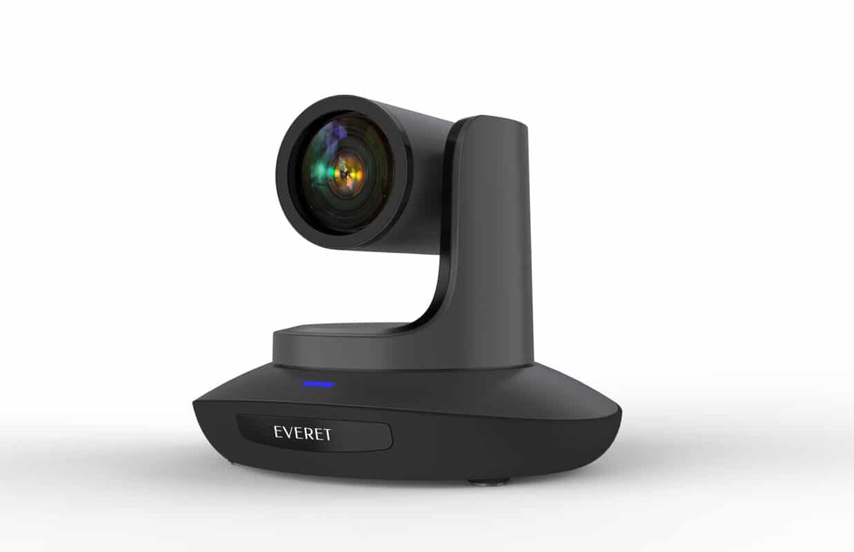
EVERET EVP220 20x FHD PTZ Video Camera
BEFORE USE
- The camera is a compact full HD camera integrated with a pan-tilt head and featuring a 1/2.8”5MP CMOS sensor and digital signal processor (DSP).
- In addition to its optical 20x zoom lens, the unit comes with a 2x digital zoom to capture high quality images.
- When a controller is connected, operations can performed smoothly via IP control or serial control.
- The camera supports standard serial communications formats, allowing connection to commercially available controllers.
- The camera is available in two color variations (white or matte black) to suit your environment and application.
- Before operation, please fully read and follow all instructions in the manual.
- The camera power input range is 100-240 VAC (50-60Hz), ensure the power supply input is within this rate before powering on.
- The camera power voltage is DC12V/8W. We suggest you use it with the original power supply adapter or use PoE+ (IEEE802.3at) compatible switch.
- Please keep the power cable, video cable and control cable in a safe place. Protect all cables especially the connectors.
- Operational environment: 0℃-50℃, humidity less than 90%. To avoid any danger, do not put anything inside the camera, and keep away from the corrosive liquid.
- Avoid stress, vibration and damp during transportation, storage and installation.
- Do not detach the camera housing and cover. For any service, please contact authorised Everet technicians.
- Video cable and control cable should be individually shielded, and cannot be substituted with other cables.
- Do not direct the camera lens towards strong light, such as the sun or the intensive light.
- Use a dry and soft cloth to clean the camera housing applied with neutral cleaning agent when needed. To avoid damage on the camera lens, never use strong or abrasive cleaning agents on the camera housing.
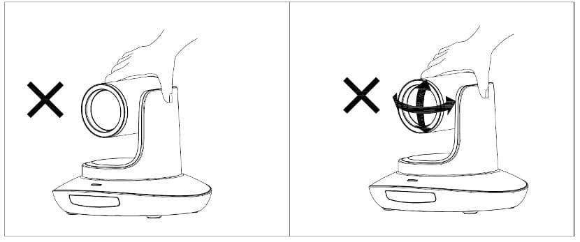
- Do not move the camera by holding the camera-head. To avoid mechanical damage do not rotate the camera-head by hand.
- NEVER MOVE THE CAMERA MANUALLY WHEN IT IS WORKING.
- Put the camera on fixed and smooth desk or platform.
- Power Supply Polarity (Drawing).
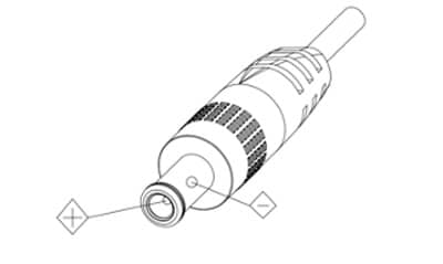
Note: The video quality may be affected by the specific frequencies of electromagnetic fields.
NEVER GRASP THE HEAD OF THE CAMERA BY HAND WHEN IT IS WORKING, OTHERWISE MECHANISM MAYBE DAMAGED.
PACKING LIST
Check all bellow items when you open the package:
| Camera | 1 |
| Power Adapter | 1 |
| Power Cable | 1 |
| RS232 Control Cable | 1 |
| USB3.0 Cable | 1 |
| Support Reference Card | 1 |
| IR Remote Controller (2x AA batteries required, not included) | 1 |
NETWORK SECURITY
If you will use the camera connected to a network, your attention is asked. It is your responsibility to take precautions such as subscribed below to protect against network security risks.
- Avoid network connections using public lines
- Use the camera in a network secured by a firewall
- Protect your network against unauthorised access by restricting users to log in with an authorised user name and password.
- Change the administrator password periodically.
- After accessing the camera as an administrator, be sure to close all web browsers.
QUICK START
- Check if following products are in the box
– Camera
– DC12V Power Adapter
– Power Cable
– RS232 Cable
– IR Remote Control - Check all cable connections before power on.
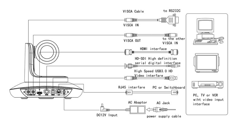
Power on the camera with the included 12V Power Adapter or use a POE+ switch
POE+ Switch Requirements:
(POE+ IEEE 802.3af/at compliant with total power of 126W up to 30W
Example recommended unmanaged POE+ network switches:
– 8-port: TL-SG1008MP
– 8-port: NETGEAR GS110TPP PoE+ Smart Switch
– 16-port: NETGEAR GS716TPP PoE+ Smart Switch
– 24-port: NETGEAR GS724TPP PoE+ Smart Switch
Example recommended managed POE+ network switches:
– 8-port: NETGEAR GSM4212P AV Line M4250-10G2F-PoE+
– 24-port: NETGEAR GSM4230P AV Line M4250-26G4F-PoE+
– 40-port: NETGEAR GSM4248P AV Line M4250-40G8F-PoE+ - Check if you get video output from HDMI or SDI on a display.
NOTE: The default resolution of the camera is 1080P30. If your display does not support this resolution you can easily change the resolution with the IR remote control. Please go to chapter: IR Remote Controller in this manual and follow instructions ‘Change video output Resolution for SDI, HDMI and USB3.0′ on how to do this. - Check if you are able to Pan and Tilt the camera with the IR remote controller.
NOTE: If you cannot pan or tilt the camera. Please go to chapter: IR Remote Controller in this manual and follow instructions ‘SET Camera 1-4′ how to do this. - Please check the default camera IP adress (192.168.1.188) for operation in your network or simply change IP adress in OSD menu settings using IR remote controller. Please go to chapter ‘OSD Menu’ and follow instructions ‘Change IP address’ how to do this.
- In the basic settings, focus, iris and white balance will be adjusted automatically (factory setting)
HOW TO TURN POWER ON AND OFF
- Set all the power switches of the camera and devices connected to ON.
- The camera does not have a power switch. When power is supplied to it, the status display LED will light up green.
- If you use POE power please check the switch is supporting POE+
(PoE+ IEEE 802.3af/at compliant with total power of 126W up to 30W per port) - Press one of the [CAM1] to [CAM4] buttons on the IR remote control to select the camera.
- Press the [ON/STANDBY] button on the remote control for 2 seconds to power on the camera
- It takes about 20 seconds per camera to start up. During this period the unit cannot be operated.
PRODUCT HIGHLIGHTS
- Panasonic 1/2.8 inch 5MP sensor providing 1080P60 full HD video
- High quality optical lens 60.5 degree field of view, 20x optical zoom, 2x digital zoom
- HDMI, 3G-SDI, USB3.0 video outputs interface
- 1080p60 video over IP, H.264, H.265 encoding
- 3G-SDI compatible with Blackmagic Design SDI Level-B
- White Balance, Exposure, Focus, Iris can be adjusted automatically or manually
- Power over Ethernet (PoE) support
- Special Focusing Algorithm: fast and precise focusing performance when zooming or moving
- Smooth PTZ mechanical design, accurate pan tilt motor control
- 128 presets supported
- Standard Sony VISCA, VISCA over IP, PELCO-P, PELCO-D control protocol; IP VISCA over both TCP and UDP
- Daisy chain supported, max 7 cameras connected in VISCA protocol
- Image flip function, support upside-down installation
- Supplied with functional IR remote controller
- Fast video format switch: less than 3 seconds
- Support RS232/RS485
- Support IR transfer function, code of the third party remote controller can be transferred to the host via VISCA IN port, in case client’s development
- OSD menu in English, IP address, streaming resolution and size can be set in OSD menu
- Matte Black and White models (W)
- 3 year warranty
- IR remote control
TECHNICAL SPECS
| Video Format HDMI (1.4) | 1920*1080P60/50/30/25/59.94/29.97/24 1920*1080i60/50/59.94 1280*720P60/50/30/25/59.94/29.97 | |
| Video Format 3G-SDI | 1920*1080P60/50/30/25/59.94/29.97/24 1920*1080I60/50/59.94 1280*720P60/50/30/25/59.94/29.97 | |
| Video Format IP | Main Stream: 1920*1080@3~60, 1280*720@3~60, 1024*576@3~60 Sub Stream: 1280*720@3~60, 1024*576@3~60 640*360@3~60 | |
| USB3.0 | 1920*1080P60/50/30/25 1280*720P60/50/30 1280*720P25 1024*576P30 960*540P30 640*360P30 352*288P30 | |
| Video Interface | HDMI (V1.4), SDI, IP, USB3.0 | |
| Audio In | none | |
| Sensor | 1/2.8” 5MP Panasonic CMOS sensor | |
| Optical Zoom | 20x | |
| Horizontal Angle | 60.00°(Far) – 3.20°(Near) | |
| Vertical Angle | 32.20°(Far) – 1.80°(Near) | |
| Aperture | F1.5 – 3.0 | |
| Focal Length | f 5.2 ~ 98mm | |
| Rotation Angle | Pan: -170° ~ +170°; Tilt: -30° ~ +90° | |
| Rotation Speed | Pan: 0°~120°/s ; Tilt: 0°~80°/s | |
| Presets | Remote controller: 10; RS232: 128; Accuracy: 0.1° | |
| Control Port | RS232, RS485, RJ45 (VISCA over IP) | |
| Network Speed | 1000M | |
| Video Encoding | H.264/H.265 (default: H.264) | |
| Bit Rate Control | Variable Bit Rate, Constant Bit Rate | |
| Video Bit Rate | 1024Kbps~16384Kbps | |
| Supported Protocols | TCP/IP, HTTP, RTSP, DHCP ,RTMP, Onvif(2.4), Visca over IP (TCP&UDP), HTML5, Visca, Pelco P, Pelco D | |
| POE | Supported PoE+ recommended (IEEE802.3at) | |
| Daisy Chain | Support RS232 serial daisy chain | |
| Minimum Lux | 0.1 lux | |
| White Balance | Auto/Indoor/Outdoor/Manual/One Push/ATW | |
| Exposure | Auto/Manual/Shutter Priority/Iris Priority/Bright | |
| Focus | Auto / Manual | |
| Iris | Auto / Manual | |
| Electric Shutter | Auto / Manual | |
| Gamma | Supported | |
| WDR | Supported | |
| BLC | Supported | |
| BLC | Supported | |
| 2D/ 3D Noise Reduction | Supported | |
| Anti Flicker | OFF/50Hz/60Hz | |
| Pan Tilt Flip | Supported | |
| Input Voltage | DC12V/8.76W PoE+ recommended (IEEE802.3at) | |
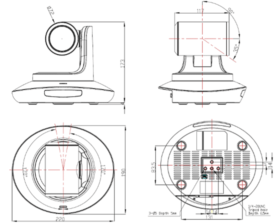
| Dimensions | 220mm×190mm×173mm | |
| Net Weight | 1.35KG | |
| EAN | 8719326505572(B) 8719327209141 (W) |
CAMERA INTERFACE
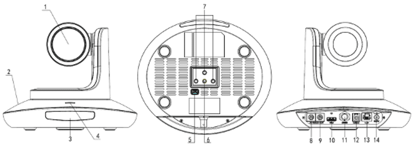
| 1.Camera Lens 2.Camera Base 3.IR Receiver Panel 4.Power Indicator Light 5.Dial Switch | 6. Tripod Screw Hole 7. Installation Hole 8. RS232 control port (input) 9. RS232 control port(output) | 10. HDMI port 11. 3G-SDI port 12. USB3.0 13. RJ45 port (IP) 14. DC12V plug |
CAMERA DIMENSIONS
DIAL SWITCH SETTINGS
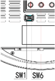
| Default Settings 1-5 OFF 6 ON | Change only when indicated by Everet Imaging Support |
IR REMOTE CONTROLLER

CHANGE VIDEO OUTPUT RESOLUTION
(for SDI, HDMI and USB3.0)
Long press one of the blue resolution buttons until the screen turns black. When the screen turns black release the button and the video output will automatically appear.
AF
Auto Focus.
MF
Manual Focus.
MENU
Enter OSD menu.
OK
Under working mode, short press OK to make the camera go back to Default PTZ position; and confirm the selection when enter OSD.
LEARN+LIMIT L key: Set the pan tilt left limit position.
LEARN+LIMIT R key: Set the pan tilt right limit position.
LEARN+LMT CLR key: Clear the limit position.
POWER
By pressing the POWER key when the camera is on, the camera will rotate and go in the ‘stand-by’ mode. When the camera is in stand-by mode and the POWER key is short pressed again, the camera will start and automatically go back to the default PTZ position. The Default PTZ position is the HOME position after self-configuration of the camera when powered on.
The only preset that overrules this Default PTZ position is the ‘0’ Preset. You can always go back to the Default PTZ position by pressing the OK button.
NOTE: The above is only applicable when solemnly IR remote control is used to control the PTZ camera. In situations where an Everet Controller (e.g. EVKB100) is used the camera Preset ‘1’ will overrule the HOME position.
FREEZE (not supported in USB)
Short press FREEZE key to freeze/ unfreeze the image.
IRT (IR Transfer/IR Pass)
Open / close the IR pass function. Once press the IRT key the camera will receive and pass the IR remote control signal to the codec / terminal (via VISCA IN port).
CAM1~CAM4(CAMERA SETTING AND SELECTION)
The SET keys are used to connect one of the CAM buttons to a specific camera. For example. If you have an EVP212, EVP220 and EVP230 and you want to configure them as follow:
CAM1 = EVP212
CAM2 = EVP220
CAM3 = EVP230
- Point the IR to camera you would like to configure.
- Long press the SET 1 button for 3 seconds until the key light of one of the CAM buttons starts flickering red.
- When this happens just release the SET button you were pressing.
- Short press CAM1 button to configure for e.g. EVP212 to CAM1.
Every time you press CAM1 you will be controlling the EVP212. You can follow these exact steps to configure other cameras.
NOTE: If you want to configure more cameras to the same CAM number than you should SET all the cameras to CAM1.
PRESET NUMBER KEY (1-9)
Set preset: long press (3 seconds) the number key to set preset.
Call Preset: Short press the number key to run preset.
CLR PRE (CLEAR PRESET)
Press CLR PRE and then choose number key of the preset you like to clear. Long press CLR PRE to clear all presets.
FOCUS KEY ( ON THE LEFT)
With this button the focus of the camera can be controlled when it is in Manual focus mode.
ZOOM KEY( ON THE RIGHT SIDE)
+ = Zoom in
– = Zoom out
NAVIGATE KEY: UP/DOWN/LEFT/RIGHT
Under working mode, use navigate key to set the pan tilt, and select menu when enter OSD.
BLC OFF/ BLC ON: Set backlight ON/OFF.
BRIGHT-/BRIGHT+: Set image brightness, only valid under bright priority exposure mode.
RESET Press 3 seconds to reset camera.
OSD MENU
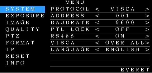
- Press the MENU key on the IR remote controller, to enter the OSD menu
- After entering the main menu, use the UP/DOWN keys on the IR remote controller to navigate through the menu. Once selected, the main menu will change to blue background, and the right side will show all sub menu options.
- Press the navigate RIGHT key to enter sub menu; use UP/DOWN key to select the submenu.
use the LEFT/RIGHT key to select parameter. - Press the MENU key again to return to previous menu. Press the MENU key continuously to exit the OSD menu. Settings that have been changed are automatically saved.
- System
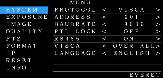
| SYSTEM | ||
| PROTOCOL | VISCA,PELCO-P,PELCO-D | Default:VISCA |
| ADDRESS | VISCA:1~7 PELCO-P/D:1~255 | Default:1 |
| BAUD RATE | 2400,4800,9600,115200 | Default:9600 |
| PTL LOCK | Protocol lock: once set, above protocol setting will be locked | Default:OFF |
| RS485 | RS485 ON/OFF | Default:OFF |
| VISCA | To select VISCA sources Optional from via COM and via IP(VISCA over IP) | Default: OVER ALL |
| LANGUAGE | English | Default:English |
- Exposure
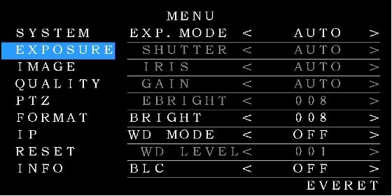
| EXPOSURE | ||
| EXPOSURE MODE | AUTO, MANUAL, SHUTTER, IRIS, BRIGHT | Default:AUTO |
| SHUTTER | Shutter speed:1/8~1/10000, only valid under manual mode | Default:AUTO |
| IRIS | Iris setting: CLOSE~F1.5, only valid under manual mode | Default:AUTO |
| GAIN | Gain setting:0dB~28dB , only valid under manual mode | Default:AUTO |
| BRIGHT | Bright setting:0~15 | Default:8 |
| EBRIGHT | Bright setting:0~15 only valid under bright priority mode. NOTE: this setting is meant to control the bright when using the EVKB-100 | Default:8 |
| WDR | ON/OFF | Default:OFF |
| WDR Level | WDR Level | Default:1 |
| BLC | ON/OFF | Default:OFF |
- Image
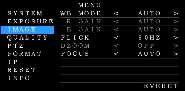
| IMAGE | ||
| WB MODE | AUTO, INDOOR, OUTDOOR, MANUAL, PUSH, ATW Auto: Automatically detects light in the room and selects the best white balance option for you. Indoor: Preset settings for indoor camera use. Outdoor: Preset settings for outdoor camera use. Manual: You Set the white balance options based on Red and Blue gains. One-Push: Used in conditions where Auto White balance is unable to detect and use a white image to auto set the white balance. Basically, you fill the frame with what you know to be a white object (even under colored lighting), this is saved as the camera’s “white” reference and camera now auto-white-balances using the new reference “white” instead of its internal reference. ATW: Auto Tracking White Balance ATW is a more dynamic version of AUTO white balance. It detects when your ambient lighting shifts significantly (such as moving from indoors to outdoors) and dynamically changes the AWB for you. | Default:AUTO |
| R/B GAIN | Red/Blue gain level: 0~255, only valid under manual white balance mode. NOTE: 0db is 100 ISO | 6db is 200 ISO | 12db is 400 ISO | 24db is 800 ISO | Default:AUTO |
| FLICK | Anti-Flicker setting:50/60HZ, to reduce the video flicker | Default:50HZ |
| DZOOM | Turn on/off digital zoom (2x digital zoom) | Default:OFF |
| FOCUS | Select focus mode: AUTO/MANUAL | Default:AUTO |
- Quality
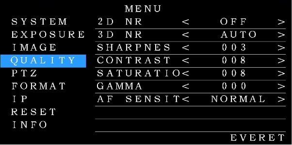
| QUALITY | ||
| 2D NR | 2D noise reduction: the bigger value, the less noise on image, the lower resolution | Default:OFF |
| 3D NR | 3D noise reduction: OFF/AUTO/0~4, the bigger value, the less motion noise on image, high value will cause image smear. | Default:AUTO |
| SHARPNESS | Sharpness setting: 0~15, the higher value, edge of the image will be sharpened | Default:AUTO |
| CONTRAST | Set contrast level | Default:50HZ |
| SATURATION | Set saturation. | Default:8 |
| GAMMA | Select gammar level | Default:0 |
| AF SENSITIVITY | Optional:LOW/NORMAL/HIGH | Default: NORMAL |
- PTZ
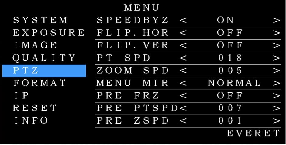
| PTZ | ||
| SPEEDBYZ | SpeedByZoom: proportional speed, the bigger zoom, the slowerspeed | Default:ON |
| FLIP.HOR | Flip horizontal | Default:OFF |
| FLIP VER | Flip vertical | Default:OFF |
| PT SPD | Pan Tilt speed | Default:18 |
| ZOOM SPD | Zoom speed | Default:5 |
| MENU MIR | Turn on/off left/menu mirror function | Default: NORMAL |
| PRE FRZ | Preset Freeze function Freeze last preset video image when switching between presets | Default: OFF |
- Format
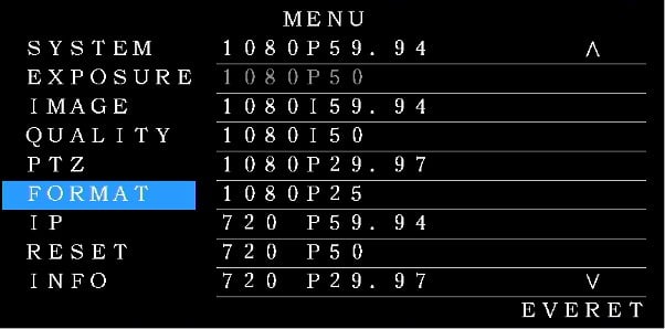
| FORMAT | ||
| 1080P60 | 1080I50 | Once selected, press OK key to confirm, if it is the selected video format, there is no change. |
| 1080P50 | 1080I59.94 | |
| 1080P30 | 720P60 | |
| 1080P25 | 720P50 | |
| 1080P59.94 | 720P30 | |
| 1080P29.97 | 720P25 | |
| 1080P24 | 720P59.94 | |
| 1080I60 | 720P29.97 |
- IP
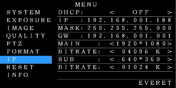
| IP | ||
| DHCP | ON/OFF | Using up/down/left/right navigation button to select item to set and using number button to set parameter. Press menu button to return. |
| IP | 192.168.001.188 | |
| MASK | 255.255.255.000 | |
| GW (Gateway) | 192.168.001.001 | |
| MAIN Stream | 1920*1080 1280*720 1024*576 | |
| BIT RATE | 10240~16384k | |
| SUB Stream | 1280*720, 1024*576,640*360 | |
| BIT RATE | 10240~16384k |
- RESET
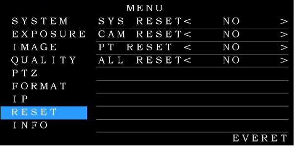
| RESET | |
| SYS RESET | Reset communication parameter to default |
| CAM RESET | Reset camera parameter to default |
| PT RESET | Reset pan/tilt parameter to default |
| ALL RESET | Reset all parameter to default |
- INFO
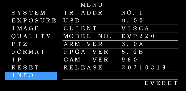
| INFO | |
| IR ADDR | Camera IR control address |
| USB | USB firmware version |
| CLIENT | Default client end protocol: VISCA |
| ARM VER | ARM firmware version |
| FPGA VER | FPGA firmware version |
| CAM VER | Camera version |
| RELEASE | Software release date |
WEB SETTINGS
Login
Run a browser and input IP address (default IP address is 192.168.1.188) to enter login interface as seen below.
Default account
Username: admin
Password: admin
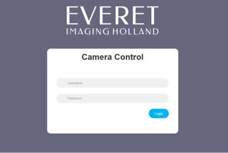
NOTE: If you cannot enter the webinterface with the default IP address there are two common situations that could be causing this problem.
PC is not in the same range as the default IP address of the camera
- In this case you would need to change the Ethernet adapter settings of your PC to get in the same IP range as the camera. Please check on the internet how to do this according to the OS system that you are using.
PC and Camera are connected to a DHCP router.
- Get into the OSD menu of the camera with the IR Remote controller.
- Navigate to IP.
- Set DHCP to ‘ON’
- Press on the menu button of the IR Remote controller until you exit.
- Restart the Camera and wait until it is completely rebooted.
- Follow steps 1 and 2, check the IP address and try to get access again in the webbrowser.
Live video image and control
After you have successfully logged in you will see the live video image of your camera as below.
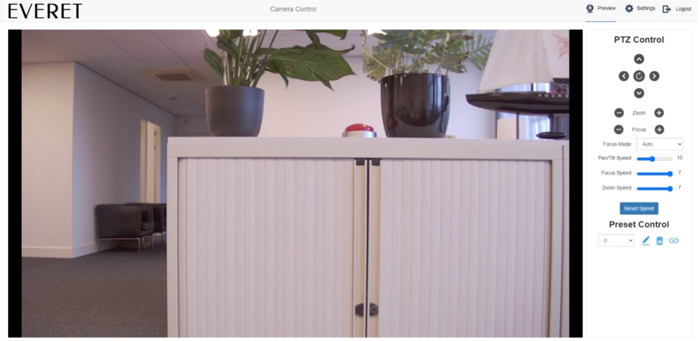
You will also be able to control following settings as you can see on the left image.
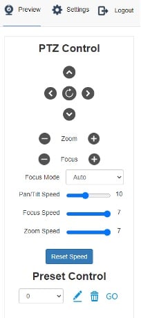
You will also be able to control following settings as you can see on the left image.
- PTZ
- Zoom
- Focus
- Focus mode
- Pan/tilt speed
- Focus speed
- Zoom speed
- Set Presets
Video Encode Settings
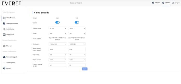
Set following settings
- Enable/disable Main or Substream
- Encode mode: H.264 / H.265
- Profile: Baseline, MP, HP
- RTSP Adress can be used to get video feed in for instance VLC or other RTSP decoders
- Resolution choose the encoding resolution
- Set your prefered bitrate
- Set Framerate
- Bitrate control: Varable or Constant Bitrate
- Set I-Frame interval
NOTE: We suggest keeping the resolution and framerate the same as your decoding project to prevent unnecessary encoding process. The I-Frame we suggest to set double as high as the framerate unless you are capturing sports or events with lots of movements per second. In that case we suggest to keep it the same as the famerate.
Video Transmission
RTMP
Real Time Messaging Protocol (RTMP) is a is a communication protocol for streaming audio, video, and data over the Internet, originally developed by Adobe for real-time streaming of video, audio, and data.
In the early days of streaming, the Real-Time Messaging Protocol (RTMP) was the de facto standard for transporting video over the internet (or in laymen’s terms, streaming). RTMP is a TCP-based protocol designed to maintain persistent, low-latency connections — and by extension, smooth streaming experiences.
Most media servers can receive RTMP. Even social media players like Facebook, YouTube, and Twitch accept it.
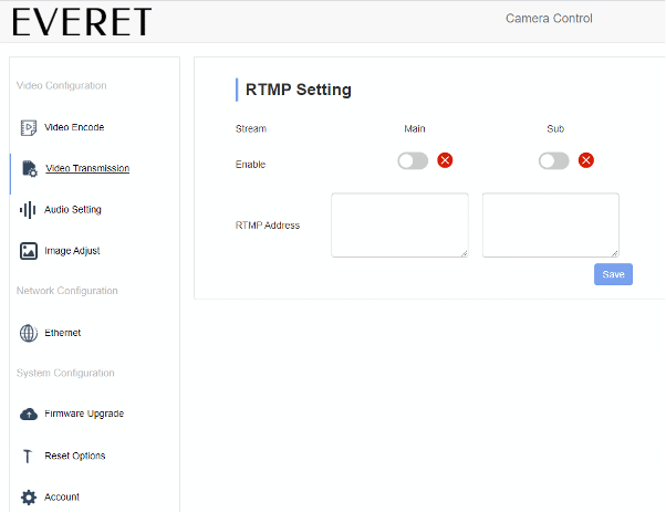
Enable RTMP streaming for e.g. YouTube or Facebook or any other RTMP address.
RTMP address: streamurl/streamkey
SRT
SRT stands for ‘Secure Reliable Transport’, and is a video streaming transport protocol designed to connect two endpoints for the purposes of delivering low latency video and other media streams across networks such as the public internet. In a nutshell, SRT brings the best quality live video over the most unreliable networks by dynamically adapting to the real-time network conditions. Compared to RTMP, SRT is more than twice as fast and when tested using dedicated hardware encoding and decoding equipment, the difference was even more with SRT being 5 to 12 times faster than RTMP.
SRT has been adopted by many of the big players in network TV, sports broadcasts and remote production. For example vMix has implemented both INPUT and OUTPUT of SRT to use remote video in a production.
Listener mode: Will listen on the specified Port for connections. Hostname is ignored.
Caller mode: Is used to connect to the specified Hostname and Port.
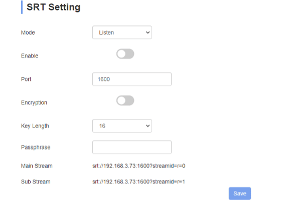
SRT Mode: Listener
Enable: enable or disable SRT stream by clicking on the “switch button”
Port: Select through which Port you want to send the SRT stream. Make sure that the caller side has the same port number.
Encryption: Enable to secure stream with a password.
Key Length: Indicates the specified key length for AES encryption.
Passphrase: fill in the password
Main/sub stream: On the caller side you need the fill in the stream ID that you want to use.
NOTE: On the caller side you only need to fill in r=0 (main stream) or r=1 (sub stream) not the entire URL.
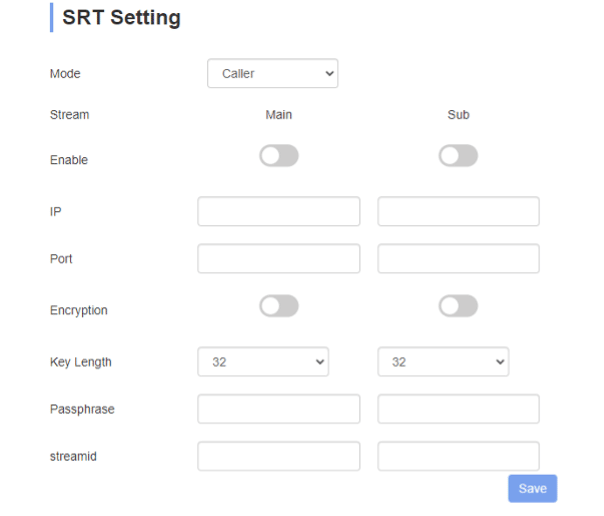
Caller mode
SRT Mode: Caller
Enable: Enable main stream and/or substream
IP: Fill in the IP address of the listener side for both main and substream
Port: Fill in the Portnumber on the listener side for both main and substream. Make sure that the sub and main stream have different portnumber when they both are enabled.
Encryption: Enable encryption
Key length: Indicates the specified key length for AES encryption.
Passphrase: fill in the password
Streamid: fill in Main stream: r=0 | Sub stream: r=1
Image Adjust
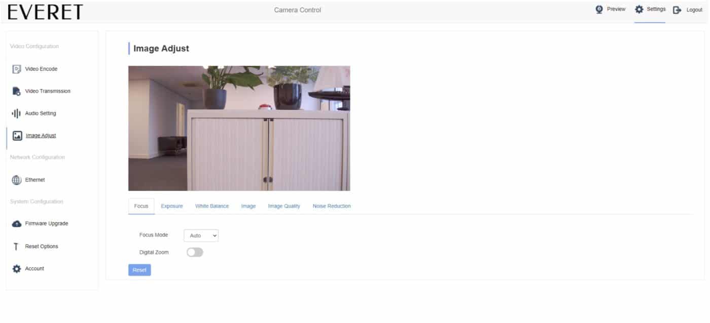
Focus
Set camera to auto or manual focus. Enable or disable Digital Zoom.
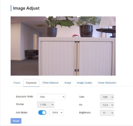
Exposure mode
Auto, Manual, Iris Priority, Shutter Priority and Brightness Priority
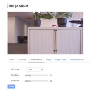
White balance mode
Auto, Indoor, Outdoor, One Push, Auto Tracking (ATW), Manual
Image
Enable mirror, flip, backlight compensation, WDR (wide dynamic range) and set Gamma.
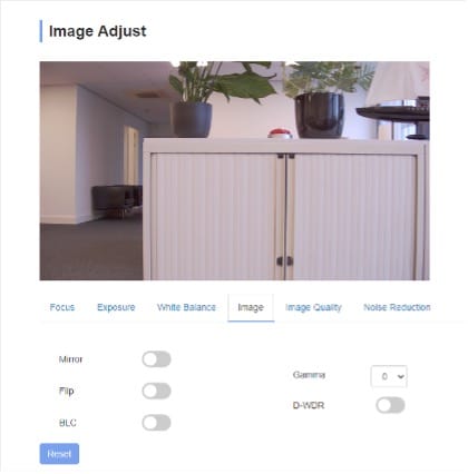
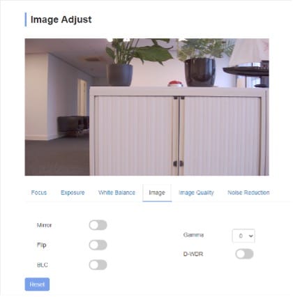
Image Quality
Configure brightness, sharpness, contrast and saturation.
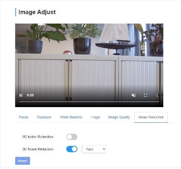
Noise reduction
Includes 2D/3D reduction. There is an on/off option for 2D, and off/auto/1~4 options.
Ethernet
In the image below you see the default Ethernet settings of the camera. This can be adjusted to your network preferences.
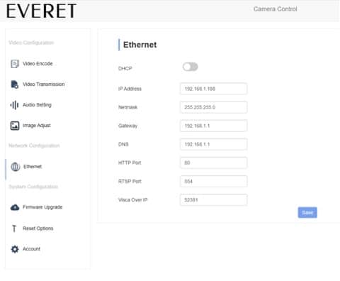
DHCP: Enable/Disable
Enable DHCP if the camera is connected to a DHCP router that dynamically grants an IP address, netmask, gateway, and DNS. When DHCP is disabled you would need to manually set the IP address, netmask, gateway, and DNS.
HTTP Port: 80
This is a standardized Port number to communicate between webclients and webservers. We suggest not to change this unless you have specific reasons.
RTSP Port: 554
This is the communication port used to stream the RTSP stream to any RTSP receiving hardware or software. We suggest not to change this unless you have specific reasons.
Visca over IP: 52381
This is the port number used to communicate PTZ commands over IP. This important if you want to control the camera with our Windows controller application, PTZ Controller and Bitfocus Companion.
Firmware Upgrade
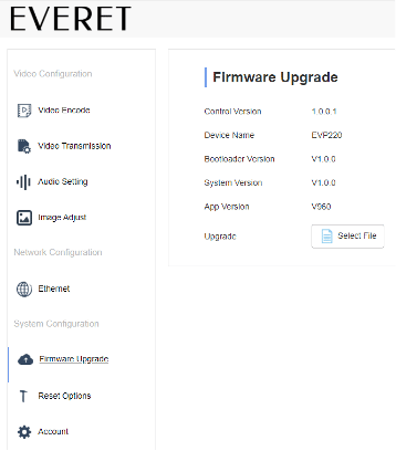
How to update
Click “select file” icon, to open dialog box, select to open the file. First upgrade the ARM file and then the ISP file. Click “upgrade” to start the upgrade process. Only use certified upgrade files from everetimaging.com support website.
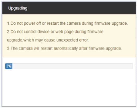
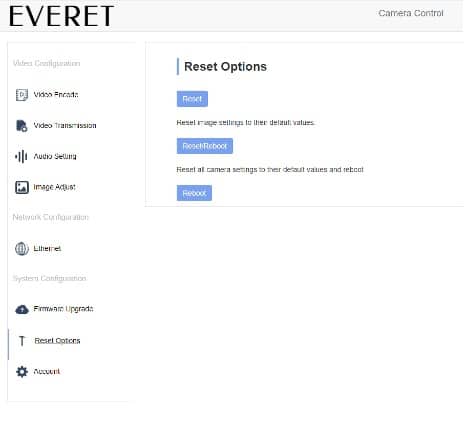
Note: DO NOT power off or take other actions during the upgrade process, the camera will reboot automatically when the upgrade is finished. Afterwards login into webinterface and select “reset all” to reset the camera completely.
Reset Options
Account Settings
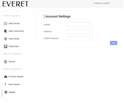
Used for setting your login username and password. First Input the accountname, then input password twice, click ok to finish settings. Please remember account and password, otherwise you are not able to login.
USING VLC TO VIEW RTSP/RTMP VIDEO
Default addresses
RTSP
- Default RTSP main streaming address: rtsp://192.168.1.188/stream/main
- Default RTSP sub streaming address: rtsp://192.168.1.188/stream/sub
RTMP
- Default RTMP main streaming address: rtmp://192.168.1.188:1935/app/rtmpstream0
- Default RTMP sub streaming address: rtmp://192.168.1.188:1935/app/rtmpstream1
1. Run VLC Media Player.
2. Select Media > network stream, to show “open media” interface.
3. Input RTSP address in URL.
4. Click play to view the real time stream.
Note: If there is to much delay, select the “more option” to change the buffer time (VLC default buffer time is 1000ms).
VISCA
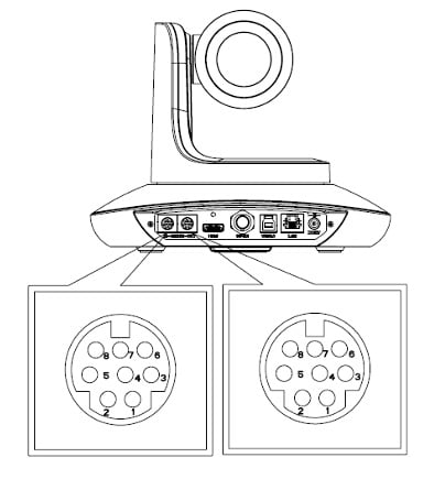
VISCA IN & Mini DIN Connection
| Camera VISCA IN | mini DIN | ||
|---|---|---|---|
| 1 | DTR | 1 | DSR |
| 2 | DSR | 2 | DTR |
| 3 | TXD | 5 | RXD |
| 4 | GND | 4 | GND |
| 5 | RXD | 3 | TXD |
| 6 | A(+) | 6 | NC |
| 7 | IR OUT | 7 | NC |
| 8 | B(-) | 8 | NC |
VISCA Network Construction
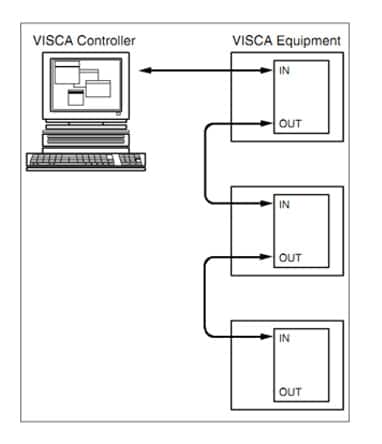
VISCA IN (RS232 PORT)
| NO | V_IN | V_OUT |
|---|---|---|
| 1 | DTR | DTR |
| 2 | DSR | DSR |
| 3 | TXD | TXD |
| 4 | GND | GND |
| 5 | RXD | RXD |
| 6 | A | |
| 7 | IR OUT | |
| 8 | B |
| VISCA IN | RS485 |
|---|---|
| 6 | A (+) |
| 7 | IR OUT |
| 8 | B (-) |
VISCA IN & DB9 Connection
| CAMERA VISCA IN | WINDOWS DB9 | ||
|---|---|---|---|
| 1 | DTR | 6 | DSR |
| 2 | DSR | 4 | DTR |
| 3 | TXD | 2 | RXD |
| 4 | GND | 5 | GND |
| 5 | RXD | 3 | TXD |
| 6 | A (+) | ||
| 7 | IR OUT | ||
| 8 | B (-) |
SERIAL PORT CONFIGURATION
| PARAMETER | VALUE | PARAMETER | VALUE |
|---|---|---|---|
| Baudrate | 2400/4800/9600/115200 | Stop Bit | 1 bit |
| Start Bit | 1 bit | Check Bit | None |
| Data Bit | 8 bit |
VISCA / PELCO COMMAND-SET
Download VISCA / PELCO commandset PDF including:
Camera return command-set
Camera control command-set
VISCA pan/tilt speed value
VISCA pan/tilt absolute position value
PELCO D protocol
PELCO P protocol
Also available as XLS file on request
VISCA OVER IP
VISCA over IP means VISCA protocol transmit via IP, to reduce RS232/RS485 cable layout (the controller must support IP communication function)
Communication port spec:
- Control port: RJ45 Gigabit LAN
- IP protocol: IPv4
- Transmit protocol: UDP
- IP address: set via web end or OSD menu
- Port address: 52381
- Confirm send/transmission control: depend on applied program
- Applied range: in the same segment, not suitable for bridged network.
- Turn on camera: In the menu, set VISCA option to OVER IP
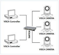
HOW TO USE VISCA OVER IP
VISCA Command
It means commands from controller to peripheral equipment, when peripheral equipment receives commands, then return ACK. When commands executed, will return complete message.
For different commands, camera will return different message.
VISCA Inquiry
It means inquiry from controller to peripheral equipment when peripheral equipment receives this kind of commands, it will return required message.
VISCA Reply
It means ACK, complete message, reply or error reply, it is sent from peripheral equipment to controller.
Command format: the following is message head and valid message format. Note: LAN output way is big-endian, LSB is in the front.
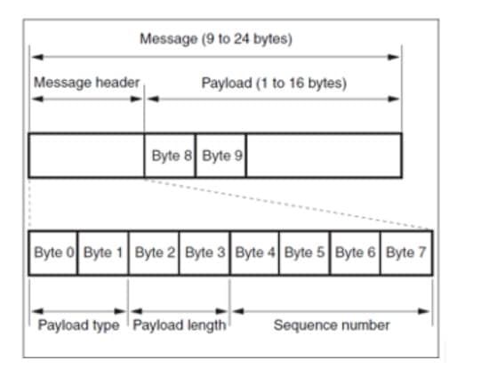
Payload type:
Data definition as following:
| Name | Value (Byte 0) | Value (Byte 0) | Value (Byte 0) |
| VISCA command | 0x01 | 0x00 | Stores the VISCA command. |
| VISCA inquiry | 0x01 | 0x10 | Stores the VISCA inquiry. |
| VISCA reply | 0x01 | 0x11 | Stores the reply for the VISCA command and VISCA inquiry, or VISCA device setting command. |
| VISCA device setting command | 0x01 | 0x20 | Stores the VISCA device setting command. |
| Control command | 0x02 | 0x00 | Stores the control command. |
| Control reply | 0x02 | 0x01 | Stores the reply for the control command. |
Payload length
Valid data length in Payload (1~16), is command length.
For example, when valid data length is 16 byte
Byte 2 : 0x00 Byte 3 : 0x10
Controller will save sequence number of each command, when one command sent, the sequence number of the command will add 1, when the sequence number becomes the max value, it will change to 0 for next time. The peripheral equipment will save sequence number of each command, and return the sequence number to the controller.
Payload
According to Payload type, the following data will be saved.
- VISCA command
Save VISCA command packet
- VISCA inquiry
Save VISCA message packet
- VISCA reply
Save VISCA return packet
- VISCA device setting command
Save VISCA equipment setting command packet.
- Control command
The following data is saved in control command payload
| Name | Value | Description |
|---|---|---|
| Reset | 0x01 | Resets the sequence number to 0. The value set as the sequence number will be ignored. |
| Error | 0x0Fyy | yy=01: Abnormality in the sequence number |
| yy=02: Abnormality in the message (message type) |
- Controlled reply
The following data is saved in return command payload of control command.
| Message | Value | Description |
| Ack | 0x01 | Reply for reset |
Delivery confirmation
VISCA over IP uses UDP as transmission communication protocol, UDP communication message transmission is not stable, it is necessary to confirm delivery and resent in application.
Generally, when controller sends a command to peripheral equipment, controller will wait for the return message then send the next command, we can detect and confirm if the peripheral equipment receive the commands from return message’s lag time. If controller shows it is overtime, it is regarded as error transmission.
If controller shows it is overtime, resend the commands to check peripheral’s status, resent command sequence number is same as last command, the following chart list the received message and status after resending the commands.
| Lost message | Received message for retransmission | Status after retransmission | Correspondence after retransmission |
|---|---|---|---|
| Command | ACK message | Command is performed by retransmission. | Continue processing. |
| ACK message | ERROR (Abnormality in the sequence number) | Command has been performed. If only the ACK message is lost, the completion message returns | If the result by the completion message is needed, retransmit by updating the sequence number. |
| Completion message for the command | ERROR (Abnormality in the sequence number) | Command has been performed | If the result by the completion message is needed, retransmit by updating the sequence number. |
| Inquiry | Reply message | Inquiry is performed by retransmission | Continue processing. |
| Reply message for the inquiry | ERROR (Abnormality in the sequence number) | Inquiry has been performed | If the result by the reply message is needed, retransmit by updating the sequence number. |
| Error message | Error message | Command is not performed. If the error cause eliminates, normal reply is returned (ACK reply message) | Eliminate the error cause. If normal reply returns continue processing. |
| Inquiry of the VISCA device setting command | Reply message of the VISCA device setting command | Inquiry has been performed by retransmission. | Continue processing. |
| Reply message of the VISCA device setting command | ERROR (Abnormality in the sequence number) | Inquiry has been performed | If the result by the reply message is needed retransmit by updating the sequence number. |
Sequence chart as following

Sequence chart when command lost and Sequence chart when returned message is lost.
Note: Do not set IP address, subnet mask, gateway parameter in VISCA over IP command, otherwise it will cause network breaks off.

