User Manual EVKB200N
Everet EVKB200 NDI® PTZ Camera Controller

Before Use
- The Everet EVKB200N is a professional NDI® Camera Controller Keyboard with PoE for PTZ cameras. Fully compatible to use different protocols to control camera simultaneously with NDI/VISCA over IP/VISCA/ONVIF/IP.
- Before using the product, please read this safety instruction carefully, operate strictly in accordance with the instruction manual, and keep this manual properly for future reference.
- The standard power supply voltage is DC 12V and the rated current is 1A. It is recommended to use with the power adapter that comes with the product or recommend PoE+ switches.
- Please place the power cable and control cable in a place where they will not be trampled on, and protect the cable, especially the connection part must be firm.
- Please use this product within the allowable temperature and humidity range. Operating temperature: -10℃~ 50℃, humidity ≤ 80%.
- Do not spill liquids, especially corrosive liquids, on this product to prevent danger.
- Please don’t put heavy pressure, violent vibration and immersion during transportation, storage and installation to avoid damaging the product.
- Please do not disassemble this product without permission, there are no parts inside the machine that can be repaired by the user, please leave the work to qualified maintenance personnel.
- Please refer to the actual product, the user manual is for reference only.
- Please contact our Customer Service Department for the latest procedures and additional documentation.
- In case of doubt or dispute in the user manual, the final interpretation of Everet shall prevail.
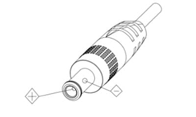
- Power Supply Polarity (Drawing).
Packing List
Check all bellow items when you open the package:
| PTZ Controller | 1 |
| Power Adapter | 1 |
| Power Cable | 1 |
| Support Reference Card | 1 |
| RS232 Female to 9-pin Male Din cable | 1 |
Network Security
If you will use the camera connected to a network, your attention is asked. It is your responsibility to take precautions such as subscribed below to protect against network security risks.
- Avoid network connections using public lines
- Use the camera in a network secured by a firewall
- Protect your network against unauthorised access by restricting users to log in with an authorised user name and password.
- Change the administrator password periodically.
- After accessing the camera as an administrator, be sure to close all web browsers.
Recommended Network Switches
POE+ Switch Requirements:
(POE+ IEEE 802.3af/at compliant with total power of 126W up to 30W
Example recommended unmanaged POE+ network switches:
- 8-port: TL-SG1008MP
- 8-port: NETGEAR GS110TPP PoE+ Smart Switch
- 16-port: NETGEAR GS716TPP PoE+ Smart Switch
- 24-port: NETGEAR GS724TPP PoE+ Smart Switch
Example recommended managed POE+ network switches:
- 8-port: NETGEAR GSM4212P AV Line M4250-10G2F-PoE+
- 24-port: NETGEAR GSM4230P AV Line M4250-26G4F-PoE+
- 40-port: NETGEAR GSM4248P AV Line M4250-40G8F-PoE
Dip Switches

| Bottom dial control | |||
| Mode | SW-1 | SW-2 | Description |
| 1 | * | OFF | ARM Upgrade Mode |
| 2 | * | ON | Normal Working Mode |
| SW-1 is reserved, no function defined | |||
Quick Start Guide
- Check if following products are in the box
– Controller
– DC12V Power Adapter
– Power Cable
– RS232 Female to 9-pin Male Din cable - Check dip switches
- Power on the controller via the DC12V adapter or a recommended switch.
- Check if you can Zoom in and Zoom out with the IR remote controller.
Key Features
- NDI®, IP & Serial Communication
- VISCA/VISCA-over-IP/Pelco-P & D Support
- 7 x Shortcut Channels, 128 Total Presets
- Power-over-Ethernet (PoE) Support
- Simultaneous Multi-Brand Camera Control
- OLED display blue for clear and easy operation
- Button backlightning
- Built-in speed rotation buttons so you can quickly and easily control the adjustment of the camera aperture, shutter, brightness and white balance
- OLED display for clear and easy operation
- 12 VDC Power Supply Included
Specifications
| Model | EVKB200N |
| Webinterface | Yes |
| DHCP | Yes |
| Display | 3.12″ OLED screen, blue light, 256×64 pixels |
| Pan & Tilt Reverse | Yes |
| Max Camera Control | |
| NDI / IP | 7 |
| Visca / RS232 / RS422 / RS485 | 7 |
| PELCO-P/D | 255 |
| Control protocols | NDI® / NDI®|HX / VISCA serial, VISCA over IP, VISCA TCP, VISCA UDP, ONVIF, PELCO-P, PELCO-D |
| Control Interface | |
| RJ45 | Ethernet port, PoE(IEEE802.3af) |
| RS232 | DB9 male connector |
| RS422 | 3.81 spacing terminal,T+,T-,R+,R- |
| RS485 | 3.81 spacing terminal,T+,T- |
| Buttons & Knobs | |
| CAM selection | Yes, (7) |
| Home (return to default PTZ position) | Yes |
| Exposure Mode | Yes |
| WB (White Balance) mode | Yes |
| Red, Blue, Gain | Yes |
| Iris | Yes |
| Shutter | Yes |
| Brightness | Yes |
| One push | Yes |
| Focus | Yes |
| Auto/Manual focus | Yes |
| Presets | Yes (128) |
| Sharpness | Yes |
| WDR (Wide Dynamic Range) | Yes |
| Contrast | Yes |
| Saturation | Yes |
| Backlight compensation | Yes |
| Preset Speed | Yes |
| Pan Tilt Speed | Yes |
| Zoom Speed | Yes |
| Zoom | Yes |
| Power/Reset | Yes |
| General | |
| Power input | DC12V 1A |
| Power Consumption | 2W |
| Operating Temperature | -10℃~50℃ |
| Operating Humidity | ≤80% |
| Storage Temperature | -20℃~60℃ |
| Storage Humidity | ≤90% |
| Dimensions | 320.5mm×156.5mm×118mm |
| Weight | 1.05 KG |
Connections

| 1. Lock hole | 5. Network interface | 9. Button |
| 2. Upgrade interface ( USB type-C) | 6. Power interface | 10. Joystick |
| 3. RS232 interface | 7. Indicator light | 11. Display screen |
| 4. RS485 interface | 8. Adjusting knob | 12. Dial switch |
Functionality Information
Display
When the EVKB200N is powered on you’ll find the information marked in blue as shown in figure below.

Buttons
In the figure below you see all the buttons and functions the EVKB200N has to offer. We will go further into details about each one in the description below.

CAM selection
The EVKB200N offers 7 shortcut CAM selection buttons. This means that you can control up to 7 cameras directly through the controller. Protocols that are supported to use all 7 are Visca over IP, Visca over UDP, Visca over TCP and NDI.
AE Mode
This is the Auto Exposure button. When the ‘AUTO’ green light is on, it means the selected camera is in Auto Exposure mode. When the light is off it means the selected camera is one of the other exposure modes. On the display you can also recognize exposure mode like shown in figure below.

Manual mode
When the selected camera is in manual mode, you can adjust following:
First Rotary knob: Shutter
Second Rotary knob: Iris
Third Rotary knob: Gain
Iris Priority mode
First Rotary knob: not functional
Second Rotary knob: Iris
Third Rotary knob: not functional
Shutter Priority mode
First Rotary knob: Shutter
Second Rotary knob: not functional
Third Rotary knob: not functional
Brightness Priority mode
First Rotary knob: not functional
Second Rotary knob: Brightness
Third Rotary knob: not functional
In the figure below is shown how you can recognize the different Exposure modes as discussed above.

WB Mode
This is the White Balance (WB) mode button. When the ‘AUTO’ green light is on, it means the selected camera is in Auto White Balance mode. When the light is off it means the selected camera is one of the other WB modes:
Indoor: when the white balance mode is in Indoor mode, you’ll see an ‘I’ on the display.
Outdoor: when the white balance mode is in Outdoor mode, you’ll see an ‘O’ on the display.
One push: when the white balance mode is in Push mode, you’ll see an ‘P’ on the display and the WB PUSH light will turn green which means the trigger button is activated to define the white scale for the camera.
Auto Tracking: when the white balance mode is in Tracking mode, you’ll see an ‘T’ on the display.
Manual: when the white balance mode is in Manual mode, you’ll see an ‘M’ on the display. Now you’ll be able to adjust the Red Gain by using the first rotary knob and the Blue Gain by using the second rotary knob.
AF/MF
This is the Auto Focus/ Manual focus button. When the green light of the AF is on this means the selected camera is in Auto Focus mode. When the green light is off this means the selected camera is in Manual focus mode. Use the third rotary know to adjust the focus of the selected camera. The PUSH FOCUS is in manual mode enabled as well. In this way you can trigger the auto focus once if you can’t find the right focus.
CALL, SET and CLEAR Presets
In the numeric button area you can SET, CALL and CLEAR up to 128 presets. Please follow instructions below to this correctly.
SET Preset: Select the number you’d like to assign to a certain preset and short press SET to save the preset. When you press the number key, you’ll see the number appear on the display. When you press SET the number will disappear which means the preset has been saved.
CALL Preset: Select the number of the preset you’d like to “Call” and short press Call/Clear button.
CLEAR Preset: Select the number of the preset you’d like the clear and long press the Call/Clear button to delete the preset. You’ll see that the number of the preset will disappear after doing this.
Parameters and Speed Adjustment Area
In this area you can adjust the parameters below.
- SHARPNESS / PRESET SPEED
- WDR / PT SPEED
- CONTRAST / ZOOM SPEED
- SATURATION / ZOOM
NOTE: Sharpness, WDR, Contrast and Saturation are only adjustable after pressing the Shift button. Once the Shift button is enabled, you’ll see this on the display as in figure below.

Other buttons
BLC ON/OFF: turn backlight compensation on/off for selected camera.
SHIFT: Sharpness, WDR, Contrast and Saturation are only adjustable after pressing the Shift button.
SEARCH: Search for IP address
HOME/OK: Return to the default position of the camera. The default position is the PTZ position the camera has after it has been powered on for the first time.
POWER/RESET: Short press to put the selected camera in stand-by mode, long press to reset the camera.
CMENU/KMENU: Short press to open the camera menu, long press to open the controller menu.
Joystick control
Up/down/left/right: use the joystick in these directions to control the Pan and Tilt
Zoom In: Turn the joystick clockwise to zoom in.
Zoom out: Turn the joystick counterclockwise to zoom out.
Lock: When controlling the camera, press the “lock” button located above the joystick, the camera keeps rotating in the previous control direction until the set lock time is exceeded or the camera rotates to the limit position.
OSD Menu
- Long press CMENU/KMENU to open the keyboard menu; Adjust the joystick Up and Down to view the menu options; Right to enter the next option; Left to return to the previous option, short press CMENU/KMENU can also return to the previous option; numeric keys 0~9 can set the corresponding parameters in some options.
- In the keyboard menu, you need to set the corresponding protocol, address to control the camera properly.
| System setting | Language | English |
| Brightness | 1~15 | |
| BackLight | AUTO/ON/OFF | |
| Screen Prt | 10s~180s | |
| DHCP | OFF/ON | |
| Local IP | 192.168.001.180(Can be set) | |
| Mask | 255.255.255.000 | |
| Gateway | 192.168.001.001 |
| Camera setting | Camera | The keyboard can be set with 7 addresses: CAM1~CAM7 |
| Protocol | VISCA Serial, Pelco-P, Pelco-D, VISCA over IP, VISCA TCP, VISCA UDP, ONVIF, NDI | |
| IP Addr / Address | Set the camera IP address or camera address. | |
| Port / Baundrate | Set the port or baud rate. Default port numbers for each IP protocol: ONVIF: 8000, NDI: 5961, VISCA: 52381 | |
| Username | Username setting, default: admin | |
| Password | Password setting, default: admin |
| PTZ setting | Pan Reverse | The left and right direction of the keyboard control can be switched. |
| Tilt Reverse | The up and down direction of the keyboard control can be switched. | |
| Preset PT Spd | Set preset PT speed: 5~24 | |
| Preset Z Spd | Set preset Zoom speed: 1~7 | |
| Foucs Speed | Set focus sensitivity: 0~7 | |
| Lock Time | Set of lock time: 2~20(s) |
| Password setting | New PSD | Set a new password to access the keyboard menu |
| Confirm | Reconfirm the new password to access the keyboard menu | |
| Enable | Password switch to access the keyboard menu | |
| Version | Keyboard program version number and update date |
IP CONTROL
In this part we will dig deeper into the different ways you can connect and control Everet Cameras using the EVKB200N via Ethernet connection.
VISCA over IP
Visca over IP is a protocol that allows for control of a device over a local network or the internet. It is an acronym for “Video System Control Architecture over IP” and is used to control cameras, robotic pan-tilt-zoom (PTZ) systems, and other video equipment. VISCA over IP uses the TCP/IP protocol to send and receive commands from a controlling device. The protocol supports multiple functions, such as controlling the camera’s zoom, focus, exposure, and shutter speed. It also supports preset operations, such as panning and tilting, as well as manual control of the camera’s position.
VISCA over IP is an efficient and reliable protocol. It is compatible with many industry-standard video devices, such as cameras, encoders, and decoders. It is also easy to set up and use, making it a great choice for controlling video equipment over a local network or the internet.
Visca over UDP
Visca over UDP is a protocol that allows control of devices such as cameras, projectors, and other devices over a local area network (LAN). It is based on the Sony VISCA protocol and is used in a variety of applications, including remote surveillance, automation, and home automation. Visca over UDP is a reliable, low-latency method of communication between devices. This is because it uses the User Datagram Protocol (UDP) for communication, which is a connectionless protocol that relies on the sending and receiving of data packets without the need for acknowledgement or retransmission. This makes it ideal for controlling devices, as the user can be sure that their commands are reaching the device in a timely fashion.
Visca over UDP is a simple protocol to implement, and it is relatively easy to use. It can be used in a variety of applications, including remote surveillance, automation, and home automation. It is highly scalable and can be used to control multiple devices from a single interface.
NDI®
NDI®camera control is a video technology designed to allow remote control of a camera. It is used by both broadcasters and video production professionals who need to be able to control their cameras from a distance. NDI® is limited in control of camera parameters:
- Pan Tilt Zoom
- Presets
- Focus ( Auto/manual)
- PT speed level 5-24
- Zoom speed level 1-7
ONVIF
ONVIF camera control is a protocol developed by the Open Network Video Interface Forum (ONVIF) to allow for the secure and reliable control of IP-based cameras. This protocol allows for the integration of different types of cameras and various control systems from different manufacturers. The protocol provides an API for connecting devices and systems, allowing for the control and configuration of devices using a single set of instructions. This makes it much easier for users to manage and configure their systems without having to learn different protocols for each system.
The ONVIF device manager is a tool to control cameras via ONVIF. See download link: https://sourceforge.net/projects/onvifdm/
Control via network switch
Before you start, please make sure you use one of the recommended switches as described in the manual of each specific camera model.
The controller connects to the switch through a network cable, and the camera connects to the switch through a network cable as well. Make sure the camera and the controller are in the same LAN, have the same network segment, corresponding protocol (Visca over IP, Visca over TCP, Visca over UDP, NDI), and port number (52381 or 5961 for NDI). When this is all correct, the camera can be controlled through the controller.
Same network segment: if the camera IP is 192.168.3.55 the controller can’t be 192.168.1.88 The 3rd number should always be the same. The 4th number needs to be different.

Control directly to the camera
In this setup the controller is connected directly to the camera through a network cable. Set the same network segment, corresponding protocol, IP address and port number, so you can control the camera through the controller.

Serial Control
Serial Protocols
There are two major serial communication protocols that are commonly used which are also supported by the controller and most cameras. These are Visca Serial and Pelco P/D. We shall give further explanation regarding both.
Visca Serial is a type of serial communication protocol used for controlling a wide variety of professional video equipment, such as cameras and switchers. It is a communication protocol based on the RS-422 standard and was developed by the Sony Corporation in the early 1990s. Visca Serial is a one-way, point-to-point communication protocol, meaning that it is only used to control one device from another device. The protocol is used to transmit commands from a controller (such as a computer, remote control, or joystick) to the device that is being controlled. The controller sends a command, and the device responds with a response.
Visca Serial has several advantages over other serial communication protocols. It can control up to 16 devices simultaneously, allowing for better control of multiple devices. It is also much faster than other serial protocols, allowing for faster response times. Additionally, Visca Serial is much more reliable than other serial protocols, due to its robust error checking and correction capabilities.
Visca Serial is widely used in the broadcast industry, and is also used in medical imaging, industrial automation, and robotics. It is also used in consumer electronics, such as home entertainment systems, security systems, and home automation systems.
The Pelco-P/D protocol can be used to control many different types of cameras and other surveillance equipment from a single controller. It is a two-way serial communication protocol that uses 8-bit words for data transmission. The protocol uses a simple, one-to-one addressing system that allows for the control of up to 32 cameras or other devices. The protocol also supports up to 31 commands for controlling pan, tilt, zoom, and focus functions.
Serial Connections
RS232, RS422 and RS485 are serial communication protocols commonly used in computer networks. They are used to transfer data between two or more devices, such as computers, printers, and other peripherals.
RS232 is the most common type of serial communication. It can be used to connect two devices up to 15 meters apart. It is typically used for lower speed data transfers such as keyboard and mouse data.
RS422 is an improved version of RS232 that can be used for higher speed data transfers over greater distances. It can be used for communication distances up to 4000 ft and can support speeds up to 10 Mbps.
RS485 is an improved version of RS422 and is used for even higher speed data transfers up to 10 Mbps. It can be used for communication distances up to 4000 ft and supports full-duplex communication, meaning that data can be sent and received simultaneously.
Overall, RS232, RS422 and RS485 are important serial communication protocols and are used in many computer networks. They each have different features and advantages which make them suitable for different types of applications.
Control via RS232
In this setup the camera is connected via RS232 cable. Set the corresponding protocol (Visca Serial), camera address and baud rate, so you can control the camera via the controller.

Using the RS232 connection, pin 1 RXD of the controller is connected to the camera input interface TXD, pin 2 TXD of the controller is connected to the camera RXD and pin 3 of the controller is connected to the camera GND. (It is also possible to use the standard RS232 interface of the control controller to connect to the camera.


| DB9 Male (Pin type) | Pin Number | 2 | 3 | 5 | 1,4,6 | 7,8 |
| Signal Definition | RXD | TXD | GND | Internal connection | Internal connection |
Control via RS422
In this setup the camera is connected via RS422 cable. Set the corresponding protocol (Visca Serial), camera address and baud rate, so you can control the camera via the controller.

Using the RS422 bus connection, the keyboard pin 1 TXD + connects to the camera’s RXD-, the keyboard pin 2 TXD – connects to the camera’s RXD +, the keyboard pin 3 RXD + connects to the camera’s TXD -, the keyboard pin 4 RXD – connects to the camera’s TXD+.

Control via RS485
In this setup the camera is connected via RS485 cable. Set the corresponding protocol
(Visca Serial, Pelco P/D), camera address and baud rate, so you can control the camera via the controller.

Using the RS485 bus connection, the keyboard pin 1 TXD + connected to the camera RXD-, the keyboard pin 2 TXD- connected to the camera RXD +.

WEBUI
In this part of the manual we shall go further into details on how you can configure the controller through the WebUI. Before you start make sure your PC/laptop is in the same network segment as the controller, otherwise you will not be able to reach the WebUI. The IP address of the controller can be found in the system settings of the controller itself. After you have successfully reached the WebUI you will be asked to login like in figure below.

Login
Default username: admin
Default Password: admin
NOTE: this can be changed in the account settings after you have logged in.
Device Control
The first thing you can do in the WebUI of the controller is search for cameras within your network and assign these to CAM 1 ~ CAM7 of the controller.

Add cameras via automatic search
When you press search, you’ll get a list of the IP addresses of the cameras that are within your network and able to connect to the controller. See figure below for an example.

You can choose via which protocol you want to control the camera. As you can see some cameras support multiple protocols. It is in that case up to you to choose the protocol you’d like to use.
After you have chosen the camera IP address and the protocol by pressing ‘add’ you can assign the camera to ID 1~7 which represent the CAM 1~7 buttons on the controller. See figure below for an example.

Add cameras manually
To add cameras manually just press ‘manually add’ next to the search button and figure below will pop up.

Now you can choose your CAM ID, IP address, Port number and Protocol.
NOTE: NDI and Visca over IP are only available when you add cameras through the search function.
When you have added some cameras you can change the CAM ID number via Config or delete completely as shown in the figure below.

Network settings
In this part of the WebUI you can change the network settings of the controller. See figure below.

DHCP: Enable/Disable
Enable DHCP if the camera is connected to a DHCP router that dynamically grants an IP address, netmask, gateway, and DNS. When DHCP is disabled, you would need to manually set the IP address, netmask, gateway, and DNS.
IP Address: When DHCP is disabled you can manually assign an IP address to the controller.
Netmask: we suggest to keep this as it is (255.255.255.0)
Gateway: make sure the 3rd number is the same as the 3rd number of your IP address when DHCP is disabled.
HTTP Port:80
This is a standardized Port number to communicate between webclients and webservers. We suggest not to change this unless you have specific reasons.
Firmware Upgrade
In the figure below you can see where you can do a Firmware Upgrade if needed. Click “select file” icon, to open dialog box, select to open the file. Only use upgrade files provided by Everet technicians or support website.


Note: DO NOT power off or take other actions during the upgrade process, the camera will reboot automatically when the upgrade is finished. Afterwards login into webinterface and select “reset all” to reset the camera completely. FW Upgrade is not possible on a MAC only Windows.
Reset/Reboot
In case you may encounter any problems with the controller we suggest to do a reset/reboot and try again. Most of the time this can solve issues controlling cameras.

Account settings
Here you can change the login username and password.

NOTE: in case you have forgotten your password you can super user account to login. username: admin password: 87866138
Trouble Shooting
| Situation | Solution Ideas |
| The controller cannot control the camera. | Check if the network cable is connected properly. |
| Check whether the camera supports the selected protocol. | |
| Check if the controller screen shows connected. The display of ” ” indicates a successful connection. | |
| Check whether the IP address, protocol and port number set on the conroller are consistent with those of the camera. | |
| Check if the keyboard and the camera are on the same LAN. | |
| Check whether the controller’s local IP address and the camera’s IP address are in the same network segment. | |
| The keyboard cannot control the camera in RS232, RS422, RS485 mode. | Check whether the RS232, RS422, RS485 cables are good and whether the interface is loose. |
| Check whether T+, T-, R+, R- of RS422 are connected wrongly; check whether T+, T- of RS485 are connected backwards. | |
| Check that the address, protocol and baud rate set on the keyboard are consistent with those of the camera. | |
| Some cameras can be controlled, some cameras cannot be controlled. | Check if the wiring of each part is normal. |
| Check that the parameters of each address code of the controller are consistent with those of the respective camera. | |
| When controlled with the controller, multiple cameras are controlled together. | Check that the protocols and addresses of the cameras being controlled together are consistent. |